기술노트 - 납산 및 리튬 배터리용 프로그램 가능한 배터리 충전기
소개
가장 쉽게 접근할 수 있는 에너지 스토리지 솔루션 중 하나인 배터리는 최근 몇 년 동안 인기를 얻고 있습니다. 오늘날 배터리는 개인용 전자제품, 자동차, UPS(무정전 전원 공급 장치) 시스템뿐만 아니라 전기 자동차와 재생 에너지 저장장치에서도 사용할 수 있다. 그러나 다양한 배터리 유형의 특성이 소비자와 엔지니어가 배터리와 충전기를 선택하는 데 기술적인 어려움을 겪고 있다. 이 자료에서는 가장 인기 있는 두 가지 배터리 유형인 납산 및 리튬 배터리 간의 차이점과 적합한 충전기를 선택하는 방법에 대해 설명합니다.
납산 및 리튬배터리의 특성
가장 인기있는 배터리 화학 유형 중 하나 인 납 축전지는 오랜 역사를 가지고 있습니다. 장점 중 일부는 높은 충전 전압 허용 오차, 높은 서지 전류 성능, 넓은 작동 온도 및 저렴한 가격입니다. 자동차 및 지게차 및 백업 시스템과 같은 동기 적용 분야에서 종종 발견됩니다. 납산 배터리의 단점은 높은 자체 방전 속도와 상대적으로 짧은 충전 / 방전주기입니다. 따라서 에너지 저장 애플리케이션에는 적합하지 않습니다.
납 산과 달리 높은 충전 / 방전 속도, 낮은자가 방전 속도 및 높은 에너지 밀도의 리튬 배터리는 장기적으로 에너지를 저장하기에 더 좋은 후보입니다. 리튬 배터리의 음극에 사용되는 금속에 따라 성능이 다른 다양한 리튬 배터리가 있습니다. 리튬 코발트 산화물 (LCO)은 에너지 밀도가 높고 개인용 전자 제품에서 널리 사용됩니다. 인산 철 리튬 (LiFePO4)은 수명이 길고 열 안정성이 상대적으로 우수하여 에너지 저장 솔루션에 더 적합한 옵션입니다. 리튬 배터리의 한계는 열 폭주로 인해 배터리에 불이 붙을 수 있다는 것입니다. 따라서 리튬 배터리는보다 신중한 충전 / 방전이 필요합니다.
배터리 충전 알고리즘
단일 납축 전지의 공칭 전압은 약 1.8-2.3V이며 권장 최대 충전 전류는 0.3C입니다. 대부분의 상용화 된 배터리는 12V, 24V 및 48V와 같은보다 실용적인 전압에서 대용량 배터리를 형성하기 위해 직렬 및 병렬로 많은 셀을 가지고 있습니다. '12V', '24V 또는'48V '는 종종 전압 범위의 표시로 느슨하게 사용됩니다. 실제 전압은 남은 용량에 따라 지속적으로 변경됩니다. 예를 들어 일반적인 '12V'AGM 납축 배터리의 개방 회로 전압은 10.8V (배터리 용량 30 %)에서 13.8V (용량 100 %) 사이입니다.
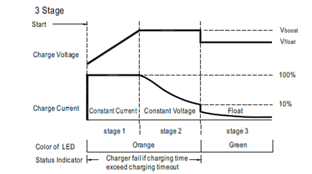
납축 배터리의 높은 자기 소산 률 때문에 3 단계 충전 방법이 권장되는 경우가 많습니다. 일반적인 충전주기는 충전기가 출력 전류를 최대 정격으로 제한하고 출력 전압을 천천히 증가시키는 정전류 단계 (그림 1의 '단계 1')에서 시작됩니다. 배터리 전압이 최대 충전 전압에 도달하면 충전기는 정전압 단계 (그림 1의 2 단계)로 전환됩니다. 충전기는 최대 정격 전압을 지속적으로 출력하고 출력 전류를 모니터링하기 시작합니다. 마지막으로 충전 전류가 정격 전류의 약 10 % 아래로 떨어지면 충전기가 부동 충전 단계 (그림 1의 '단계 3')로 변경됩니다. 이 단계에서 충전기는 과충전을 피하기 위해 출력 전압을 낮 춥니 다. 이 시점에서 배터리는 거의 완전히 충전되고 있지만 자체 소실을 보상하기 위해 계속해서 충전기에서 전력을 끌어옵니다.
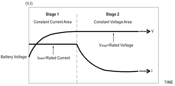
리튬 배터리는 최대 충전 전류가 최대 1C 인 3.2V ~ 4.4V의 공칭 전압을 가질 수 있습니다. 리튬 배터리의 화학적 변형이 동일하지만 제조업체가 다르더라도 정격 전압과 충전 전류가 다를 수 있습니다. 납축 배터리와 달리 리튬 배터리는 높은 충전 전압을 허용하지 않으며 충전 상태를 유지하기 위해 부동 충전이 필요하지 않습니다. 따라서 리튬 배터리는 부동 충전 단계없이 2 단계 충전 방법 (그림 2)으로 충전되는 경우가 많습니다.
셀 불균형은 대형 리튬 배터리 뱅크의 문제입니다. 제조 공차로 인해 리튬 전지의 등가 직렬 저항 (ESR)은 완벽하게 일치 할 수 없습니다. 셀 간의 차이로 인해 동일한 뱅크의 셀이 다른 전압 또는 전류로 충전 될 수 있습니다. ESR이 낮은 셀은 항상 먼저 완전히 충전 / 방전되므로 이러한 셀은 더 빨리 노화되고 실패합니다. 셀의 불균형은 배터리 수명을 단축시킬뿐만 아니라 잠재적으로 열 폭주를 유발하고 안전 위험이 될 수 있습니다. 이 문제를 해결하려면 대형 리튬 배터리 뱅크에는 항상 배터리 관리 시스템 (BMS)이 장착되어 있어야합니다. BMS의 기본 기능은 충전 상태를 모니터링하고 수동 또는 능동적으로 셀의 균형을 유지하는 것입니다. 패시브 BMS는 전력 저항을 사용하여 더 많은 셀을 방전하여 셀의 균형을 맞 춥니 다. 견고하고 상대적으로 설계하기 쉽지만 효율적이지 않고 덜 효과적입니다. 반면에 활성 BMS는 충전 상태와 일치하도록 셀을 개별적으로 충전합니다. 액티브 BMS에는 각 셀에 대한 충전 제어 기능이 있기 때문에 액티브 밸런싱 BMS가있는 일부 리튬 배터리 뱅크에는 충전기로 정전압 AC / DC 전원 공급 장치 만 필요합니다.
민웰 스마트 배터리 충전 솔루션
위에서 언급했듯이 화학 및 제조업체가 다른 배터리는 다른 특성을 가질 수 있습니다. 또한 신뢰성, 수명 및 안전성을 보장하기 위해 배터리에 최적화 된 충전 곡선을 갖는 것이 좋습니다 (리튬 배터리의 경우 필수). 스마트 충전기 프로그래머 SBP-001이 포함 된 MEAN WELL 프로그래밍 가능 충전기는 충전 곡선을 조정할 수있는 유연성과 사용자 친화적 인 인터페이스를 제공합니다.
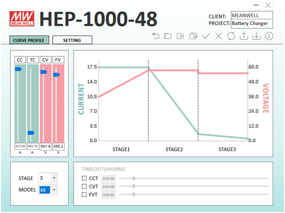
최근 출시 된 HEP-1000 시리즈를 예로 들어 보겠습니다. HEP-1000-48의 기본 설정은 48V 및 최대 1008W 정전압 전원 공급 장치입니다. 사용자는 MEAN WELL 스마트 충전기 프로그래머 SBP-001과 HEP-1000-48을 연결하고 충전기 모드를 활성화 할 수 있습니다. 기본 충전 곡선은 57.6V 부스트 충전 전압과 55.2V 부동 충전 전압을 사용하는 일반적인 밀폐형 납축 배터리의 3 단계 (그림 3)입니다. 충전 전압 및 전류는 다른 유형의 납축 배터리에 대해 각각 36 ~ 60V 및 3.5 ~ 17.5A로 쉽게 조정할 수 있습니다.
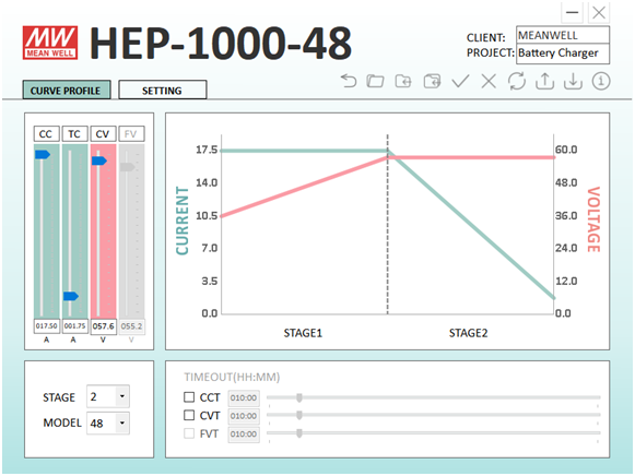
2 단계 충전 모드를 선택하기 만하면 HEP-1000은 동일한 조정 범위로 리튬 배터리를 충전하는 데에도 사용할 수 있습니다. 최대 충전 전압이 56V 인 20Ah LiFePO4 배터리를 충전하려면 그림 4에 표시된 'CV'및 'CC'옵션을 56V 및 17.5A로 설정하여 가장 빠른 충전을 할 수 있습니다. 사용자는 과충전의 가능성을 피하기 위해 높은 전류로 인한 온도 상승과 낮은 전압을 방지하기 위해 충전 전류를 낮출 수도 있습니다.
결론
결론적으로, MEAN WELL 프로그래밍 가능 충전기를 사용하여 납산 또는 리튬 배터리에 필요한 충전 곡선을 맞춤화 할 수 있습니다. 배터리의 온도와 수명에 따라 충전 전압과 전류를 조정하면 배터리를 보존하고 용량을 최적화 할 수 있습니다.
Introduction
Battery, as one of the easiest accessible energy storage solutions, has been gaining popularity in recent years. Nowadays, batteries not only can be used in personal electronics, cars, and uninterrupted power supply (UPS) systems but also in electrical vehicles and renewable energy storage. However, different characteristics of different battery types post technical challenges for consumers and even engineers to select batteries and chargers. This article will discuss the differences between two of the most popular battery types: Lead Acid and lithium battery as well as how to select a suitable charger.
Characteristics of Lead Acid and Lithium Batteries
Lead-Acid batteries as one of the most popular battery chemistry types had a long history. Some of the advantages are high tolerance of charging voltage, high surge current capability, wide operating temperature, and low price. It is often found in motive applications such as cars and forklifts as well as back-ups systems. The drawbacks of Lead-acid batteries are the high self-discharging rate and relatively short charge/discharge cycles; hence it is not suitable for energy storage applications.
Contrary to lead-acid, the high charging/discharging rate, low self-discharge rate, and high energy density of lithium batteries make it a better candidate for storing energy for a longer-term. Depending on the metal used on the cathode of lithium batteries, there are a variety of lithium batteries with different performances. Lithium cobalt oxide (LCO) has a high energy density and is popular in personal electronics. Lithium iron phosphate (LiFePO4) has a longer lifetime and relatively good thermal stability making it a better option for energy storage solutions. The limitation of lithium batteries is that thermal runaway could cause the battery to catch on fire. Therefore, lithium batteries require more deliberate charging/discharging.
Battery Charging Algorithm
The nominal voltage of a single lead-acid cell is about 1.8-2.3V with recommended max charging current of 0.3C. Most commercialized batteries have many cells in series and parallel to form a large capacity battery at more practical voltages like 12V, 24V, and 48V. Note the ‘12V’, ‘24V, or ‘48V’ is often used loosely as an indication of the voltage range. The actual voltage would constantly change based on the remaining capacity. For example, the open-circuit voltage of a typical ‘12V’ AGM lead-acid battery is between 10.8V (30% battery capacity) to 13.8V(100% capacity).
Because of the high self-dissipation rate of lead-acid batteries, the 3-stage charging method is often recommended. A typical charging cycle starts at the constant current stage (‘stage 1’ of Figure 1) which the charger limits its output current to its max rating and slowly increases its output voltage. Once the battery voltage reaches the max charging voltage, the charger would switch to a constant voltage stage (‘stage 2’ of Figure 1). The charger starts outputting its max rated voltage constantly and monitoring its output current. Finally, the charger changes to the floating charging stage (‘stage 3’ of Figure 1) after the charging current drop below about 10% of the rated current. At this stage, the charger would lower its output voltage to avoid overcharging. Although the battery at this point is close to being fully charged, it would still constantly draw power from the charger to compensate for its self-dissipation.
Lithium batteries could have nominal voltages from 3.2V to 4.4V with a max charging current up to 1C. Even the same chemistry variant of lithium batteries but from different manufacturers could have different rated voltage and charging current. Unlike Lead Acid batteries, lithium batteries do not tolerate high charging voltage and do not require floating charging to maintain their state of charge. Therefore, lithium batteries are often charged with a 2-stage charging method (Figure 2) without the floating charging stage.
Cell imbalance is a concern for a large lithium battery bank. Due to the manufacturing tolerances, equivalent series resistance (ESR) of lithium cells cannot be matched perfectly. The differences among cells cause cells in the same bank could be charged at a different voltage or current. The cells with low ESR will always be fully charged/discharged first, so those cells will age and fail faster. The imbalance of cells not only shortens the lifetime of the battery but also could potentially cause thermal runaway and become a safety hazard. To solve this issue, large lithium battery banks should always be equipped with battery management systems (BMS). The basic function of BMS is monitoring the state of charge and balancing cells either passively or actively. The passive BMS balances cells by discharging the fuller cells using power resistors. It is robust and relatively easy to design, but not efficient and less effective. On the other hand, the active BMS charges cells individually to matches the states of charge. Because active BMS has charging control for each cell, some lithium battery bank with active balancing BMS only require constant voltage AC/DC power supplies as the charger
MEAN WELL Smart Battery Charging Solution
As mentioned above, batteries of different chemistry and from different manufacturers could have different characteristics. It is also recommended (mandatory for Lithium batteries) to have the charging curve optimized for batteries to ensure reliability, longevity, and safety. MEAN WELL programmable chargers with the smart charger programmer SBP-001 offers flexibility and a user-friendly interface for adjusting the charging curve.
Using the recently released HEP-1000 series as an example. The default setting of HEP-1000-48 is a 48V and max 1008W constant voltage power supply. Users can connect HEP-1000-48 with MEAN WELL smart charger programmer SBP-001 and enable the charger mode. The default charging curve is a 3-stage (Figure 3) for typical sealed lead-acid batteries with a 57.6V boost charging voltage and 55.2V floating charging voltage. The charging voltage and current can be easily adjusted to 36~60V and 3.5~17.5A respectively for other types of lead-acid batteries
By simply selecting the 2-stage charging mode, HEP-1000 also can be used for charging lithium batteries with the same adjustment range. For charging a 20Ah LiFePO4 battery with a max charge voltage of 56V, the ‘CV’ and ‘CC’ option shown in Figure4 can be set to 56V and 17.5A for fastest charging. The user could also lower the charging current to prevent high current caused temperature rise and lower voltage to avoid the possibility of overcharging.
Conclusion
In conclusion, MEAN WELL programmable chargers can be used to accommodate the customization of charging curves required by either lead-acid or lithium batteries. Adjusting the charging voltage and current based on the temperature and age of the battery could also preserve the battery and optimize its capacity.


